
The Retractable Chemical Injection Quill is an advanced mechanism designed for precise and controlled injection of chemical inhibitors into pipelines, critical for minimizing or controlling corrosion. This device forms an integral part of the EMT Injection System, known for its reliable and safe operation under full system pressure.
1. Parameter Table
Access Fitting Body
| Model | ||||||
| EMT-CIPA | Retractable Chemical Injection Quill | |||||
| – The material of Access Fitting Body | ||||||
| 0 | CS | |||||
| 1 | 316SS | |||||
| 2 | 316LSS | |||||
| 3 | DUPLEX SS | |||||
| The Type of Access Fitting Body | ||||||
| B | 2″Welded(suffix “pressure rating” can be added to B) | |||||
| F | 2″ANSI Flange(suffix “pressure rating & sealing type” can be added to F) | |||||
| -Tee Size- pressure rating & sealing type if flanged end | ||||||
| 0 | No Tee | |||||
| 1 | 1/4″NPT(F)Tee | |||||
| 2 | 1/2″NPT(F)Tee | |||||
| 3 | 3/4″NPT(F)Tee | |||||
| 4 | 1″NPT(F)Tee | |||||
| 5 | Hole for 1/4″SWN Flange | |||||
| 6 | Hole for 1/2″SWN Flange | |||||
| 7 | Hole for 3/4″SWN Flange | |||||
| 8 | Hole for 1″SWN Flange | |||||
| -Protective Cover Type/ Material | ||||||
| 0 | No Protective Cover | Material | ||||
| 1 | Without hole | CS or 0 | ||||
| 2 | With hole | SS or 1 | ||||
| 3 | Bleed Valve | DSS or 3 | ||||
| 4 | Bleed Valve, & Pressure Gauge | |||||
| For Example:EMT-CIPA-0F600#RF-2-1/CS shows 2″ANSI 600#RF Flange Access Fitting Body in CS, 1/2″NPT(F)Tee, Protective Cover in CS without hole 0F600#RF: 0F_ Access Fitting Body is Flanged in CS , 600#RF _Size is 2″ANSI 600#RF , 2:Tee size is 1/2NPT(F) 1: Protective cover type is without hole /CS: Protective cove material in CS | ||||||
Sampler & Injector
| Model | |||||||||||||||||||||||||
| SI | Sampler & Injector Retractable Chemical Injection Quill | ||||||||||||||||||||||||
| -Code | Plug | ||||||||||||||||||||||||
| Pxxx | Type | Material | Sealing Material | ||||||||||||||||||||||
| 0 | No Request | 0 | CS | 0 | No Request | ||||||||||||||||||||
| 1 | Hollow Plug Body | 1 | 316SS | 3 | DSS | 1 | Viton O-Ring / PTFE Primary Packing | ||||||||||||||||||
| 2 | Solid Plug Body | 2 | 316LSS | 4 | INCONEL | 2 | HNBR | ||||||||||||||||||
| – Code | Injection Nut | ||||||||||||||||||||||||
| Nxx | Connection Size | Material | |||||||||||||||||||||||
| 0 | No Request | 0 | CS | ||||||||||||||||||||||
| 1 | 1/4″ | 1 | 316SS | 3 | DSS | ||||||||||||||||||||
| 2 | 1/2″ | 2 | 316LSS | 4 | INCONEL | ||||||||||||||||||||
| – Code | Sampling & Injection Tube | ||||||||||||||||||||||||
| Sxxx-Lx″ | Connection Size | Material | Nozzle | Line size(x″) | |||||||||||||||||||||
| 0 | No Request | 0 | CS | 0 | No Request | The most effective position for injection is generally at the center of the pipe | |||||||||||||||||||
| 1 | 1/4″ | 1 | 316SS | 1 | Open | ||||||||||||||||||||
| 2 | 1/2″ | 2 | 316LSS | 2 | Quill | ||||||||||||||||||||
| 3 | DSS | 3 | Cap & Core | ||||||||||||||||||||||
| 4 | INCONEL | ||||||||||||||||||||||||
| – Code | Type and Size of components connected to Tee and material of components | ||||||||||||||||||||||||
| Txx | Connection Size | Material | |||||||||||||||||||||||
| 0 | No Request | 0 | CS | ||||||||||||||||||||||
| 1 | 1/4″Nipple | a | 1/4″Nipple and Valve | 1 | 316SS | ||||||||||||||||||||
| 2 | 1/2″Nipple | b | 1/2″Nipple and Valve | 2 | 316LSS | ||||||||||||||||||||
| 3 | 3/4″Nipple | c | 3/4″Nipple and Valve | 3 | D SS | ||||||||||||||||||||
| 4 | 1″Nipple | d | 1″Nipple and Valve | 4 | INCONEL | ||||||||||||||||||||
| 5 | 1/4″SWN Flange* | e | 1/4″Nipple and Flange | ||||||||||||||||||||||
| 6 | 1/2″SWN Flange | f | 1/2″Nipple and Flange | ||||||||||||||||||||||
| 7 | 3/4″SWN Flange | g | 3/4″Nipple and Flange | ||||||||||||||||||||||
| 8 | 1″SWN Flange | h | 1″Nipple and Flange | ||||||||||||||||||||||
| For Example:SI-P221-N12-S122-L4″-T22 SI:Sampling & Injection Assembly,P221: Solid Plug Body in 316LSS Viton O-Ring and PTFE Primary Packing,N12:Injection Nut Connection Size is 1/4″and Material is 316LSS,S122:Injection Tube Connection Size is 1/4″ and Material is 316LSS.Type of nozzle is quill,L4″:For 4″pipe. T22: Connection Size of Nipple connected to Tee is 1/2″NPT(M), Nipple material is 316LSS | |||||||||||||||||||||||||
Note: SWN Flange is special WN Flange
Example for a set of Sampler & Injector Assembly:
EMT-CIPA-0F600#RF-2-1+ SI-P221-N12-S122-L4″-T22
2. Key Features of the Retractable Chemical Injection Quill:
Versatile Design:
The quill is equipped with a variety of nozzle options to cater to different injection requirements, ensuring efficient delivery of chemical inhibitors directly into the pipeline system. This design allows for the adaptation to varying flow rates and viscosities of the injected chemical .
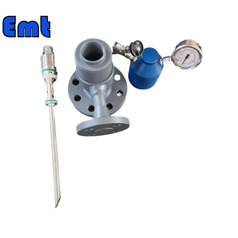
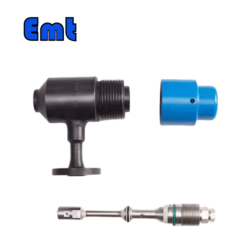
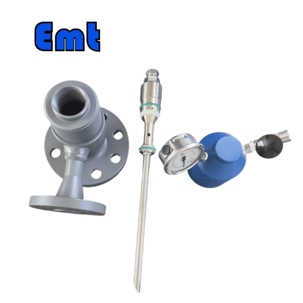
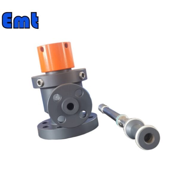
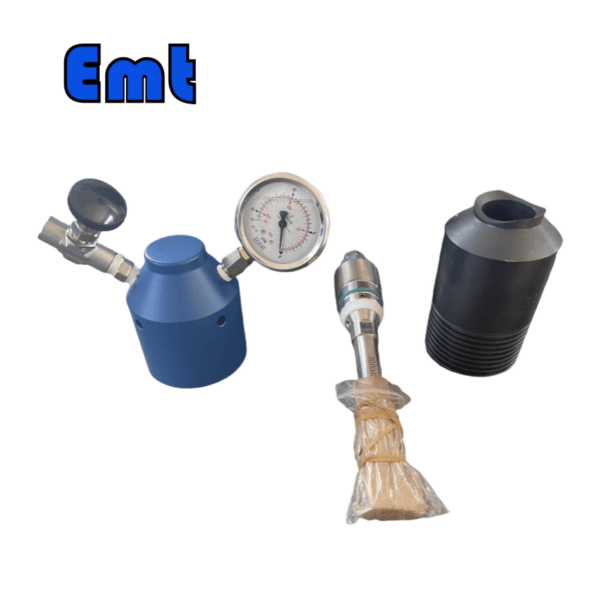
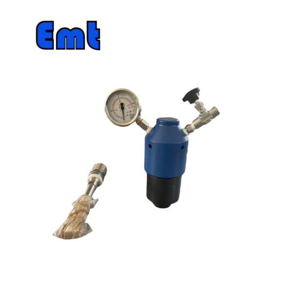
Robust Internal Assembly:
The internal components of the quill include a solid plug body, an injection nut, and an injection tube, all engineered to ensure durability and reliability. These components are connected to a Tee assembly that includes an NPT nipple, a valve, and an SWN flange to secure and stabilize the installation.
Flexible Process Connections:
The quill supports multiple connection sizes, including a 2″ flange, 2″ Flareweld access fitting, and 1″ Nipple to NPT ball valve, offering flexibility to match specific pipeline configurations and requirements.
High Operational Standards:
Designed to operate effectively within a temperature range of -20 ℃ to 150 ℃ and withstand pressures up to 6000 PSI, the quill is suitable for harsh environments and high-pressure applications typical in industrial settings.
3. Customization Options:
The EMT Injection System offers extensive customization through its varied Access Fitting Body options, such as:
- Material Options. Available in Carbon Steel (CS), 316 Stainless Steel (316SS), 316L Stainless Steel (316LSS), and DUPLEX Stainless Steel (DUPLEX SS).
- Connection Types. Options include a 2″ Welded configuration or a 2″ ANSI Flange, with additional specifications for pressure ratings and sealing types.
- Tee Sizes. Various Tee sizes are available ranging from 1/4″ NPT to 1″ NPT, as well as options for SWN Flange connections.
- Protective Cover Types. Choices range from no protective cover to covers equipped with or without holes, with bleed valves, and options for integrating pressure gauges.
4. Example Configuration:
For instance, an EMT-CIPA model with the specification 0F600#RF-2-1/CS includes a 2″ ANSI 600#RF Flange Access Fitting Body in Carbon Steel, a 1/2″ NPT(F) Tee, and a protective cover in Carbon Steel without holes. This demonstrates the modularity and adaptability of the system to meet specific operational needs and environmental conditions.
There are no reviews yet.