
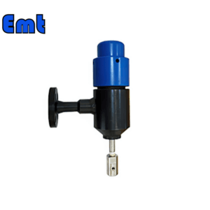
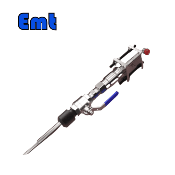
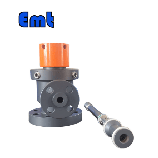
A Chemical Injection Quill is an essential device designed for safely introducing corrosive chemicals into a pipeline system. Its primary function is to ensure that these chemicals are evenly dispersed at the center of the pipeline. This even dispersion is crucial as it prevents the chemicals from merely flowing along the pipeline’s channels, which could lead to uneven distribution and potential inefficiencies in the process.
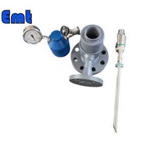
Moreover, the Injection Quill plays a vital role in protecting the integrity of the pipeline. By directing chemicals to the center, it helps avoid direct contact with the pipeline walls or side ports, thereby reducing the risk of corrosion and damage over time.
The working principle of a Chemical Injection Quill typically involves using an electric pump. This pump is responsible for forcibly injecting the liquid chemicals through a connecting pipe under controlled pressure. This method ensures precise and effective delivery into the pipeline system.
Before diving deeper into the specifics of the Injection Quill, it’s beneficial to understand some basics about pipeline maintenance, which ensures the long-term efficiency and safety of these systems.
Parameters
| Category | Details |
| Product Information | |
| Product Name | Chemical Injection Quill |
| Brand Name | EMT Pigging |
| Condition | New |
| Type | Injection & Sampling System |
| Certification | ISO 9001 |
| Warranty | 1.5 years |
| Place of Origin | Liaoning, China |
| Physical Specifications | |
| Weight (KG) | 5 |
| Package Size (cm) | 35 x 40 x 60 |
| Gross Weight (Package, kg) | 8 |
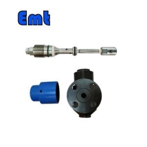
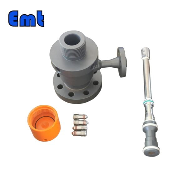
| Material and Construction | |
| Sealing Material | Fluororubber |
| Solid Plug Assembly | 316L Stainless Steel |
| Injection Tube | 316L Stainless Steel |
| NPT Nozzle | 316L Stainless Steel |
| Flange Material | ASTM A105N |
| Operational Parameters | |
| Working Temperature (°C) | -20 to 200 |
| Operation Temperature (°C) | -20 to 150 |
| Working Pressure (LB) | 150LB, 300LB, 600LB, 900LB, 1500LB |
| Pressure Rating (PSI) | 6000 PSI or as per Flange Size |
Oil and Gas Pipeline Corrosion Maintenance
Oil and gas pipeline corrosion maintenance is crucial for ensuring the safety and longevity of these infrastructures. To prevent corrosion, companies often apply protective coatings and linings to the pipeline surfaces. These barriers help prevent direct contact between the pipeline material and corrosive substances, significantly reducing the risk of damage.
Another effective technique is cathodic protection, which involves the use of electrical currents to counteract the natural corrosion process. Additionally, corrosion inhibitors—specialized chemicals—are injected into the system to slow down or prevent corrosion. These methods collectively help maintain the integrity of the pipelines.
Monitoring and inspection play a vital role in corrosion maintenance. Regular inspections, including visual checks and the use of pigging devices, are essential for early detection of corrosion. Corrosion test coupons, which involve inserting and analyzing metal samples within the pipeline, provide valuable data on corrosion rates. Advanced technologies like ultrasonic testing offer detailed assessments without damaging the pipeline.
Implementing robust maintenance strategies is essential for preventing corrosion. Preventive maintenance involves scheduling regular checks to address potential issues before they escalate. Predictive analytics, which uses data to foresee and mitigate future corrosion problems, is becoming increasingly popular. By maintaining pipelines effectively, companies can minimize risks, reduce repair costs, and ensure efficient operations.
How to Protect Oil and Gas Pipelines by using Chemical Injection Quill?
To protect oil and gas pipelines using a Chemical Injection Quill, follow these steps:
1. Select Appropriate Chemicals
Choose corrosion inhibitors that are compatible with both the pipeline material and the transported substances.
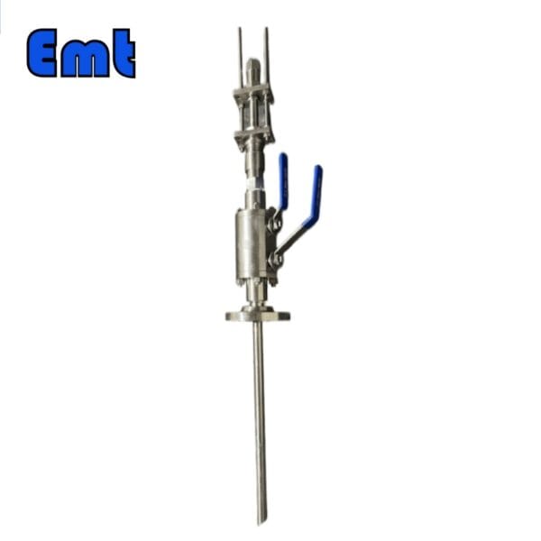
2. Proper Installation
Install the injection quill at strategic points to ensure even distribution of chemicals. Position it at the pipeline’s center to avoid contact with the walls.
3. Controlled Injection
Use an electric pump to inject chemicals at the right pressure. This ensures consistent and effective dispersion throughout the pipeline.
4. Regular Monitoring
Continuously monitor the injection process to adjust chemical concentrations as needed. Use sensors to track effectiveness and corrosion rates.
5. Routine Maintenance
Perform regular checks on the quill and injection system to prevent blockages and ensure optimal performance.
Selection Model
| Model | |||||||||||||||||||||||||||
| SI | Chemical Injector Quill | ||||||||||||||||||||||||||
| -Code | Plug | ||||||||||||||||||||||||||
| Pxxx | Type | Material | Sealing Material | ||||||||||||||||||||||||
| 0 | No Request | 0 | CS | 0 | No Request | ||||||||||||||||||||||
| 1 | Hollow Plug Body | 1 | 316SS | 3 | DSS | 1 | Viton O-Ring / PTFE Primary Packing | ||||||||||||||||||||
| 2 | Solid Plug Body | 2 | 316LSS | 4 | INCONEL | 2 | HNBR | ||||||||||||||||||||
| – Code | Injection Nut | ||||||||||||||||||||||||||
| Nxx | Connection Size | Material | |||||||||||||||||||||||||
| 0 | i.e. No Request | 0 | i.e. CS | ||||||||||||||||||||||||
| 1 | i.e. 1/4″ | 1 | i.e. 316SS | 3 | i.e. DSS | ||||||||||||||||||||||
| 2 | i.e. 1/2″ | 2 | i.e. 316LSS | 4 | i.e. INCONEL | ||||||||||||||||||||||
| – Code | Injection Tube | ||||||||||||||||||||||||||
| Sxxx-Lx″ | Connection Size | Material | Nozzle | Line size(x″) | |||||||||||||||||||||||
| 0 | No Request | 0 | CS | 0 | i.e. No Request | The most effective position for injection is generally at the center of the pipe | |||||||||||||||||||||
| 1 | i.e. 1/4″ | 1 | i.e. 316SS | 1 | i.e. Open | ||||||||||||||||||||||
| 2 | i.e. 1/2″ | 2 | i.e. 316LSS | 2 | i.e. Quill | ||||||||||||||||||||||
| 3 | i.e. DSS | 3 | i.e. Cap & Core | ||||||||||||||||||||||||
| 4 | i.e. INCONEL | ||||||||||||||||||||||||||
| – Code | Nipple and Valve(or end Flange)of Tee | ||||||||||||||||||||||||||
| Txx | Connection Size | Material | |||||||||||||||||||||||||
| 0 | i.e. No Request | 0 | i.e. CS | ||||||||||||||||||||||||
| 1 | i.e. 1/4″Nipple | a | i.e. 1/4″Nipple and Valve | 1 | i.e. 316SS | ||||||||||||||||||||||
| 2 | i.e. 1/2″Nipple | b | i.e. 1/2″Nipple and Valve | 2 | i.e. 316LSS | ||||||||||||||||||||||
| 3 | i.e. 3/4″Nipple | c | i.e. 3/4″Nipple and Valve | 3 | i.e. D SS | ||||||||||||||||||||||
| 4 | i.e. 1″Nipple | d | i.e. 1″Nipple and Valve | 4 | i.e. INCONEL | ||||||||||||||||||||||
| 5 | i.e. 1/4″Flange | e | i.e. 1/4″Nipple end Flange | ||||||||||||||||||||||||
| 6 | i.e. 1/2″Flange | f | i.e. 1/2″Nipple end Flange | ||||||||||||||||||||||||
| 7 | i.e. 3/4″Flange | g | i.e. 3/4″Nipple end Flange | ||||||||||||||||||||||||
| 8 | i.e. 1″Flange | h | i.e. 1″Nipple end Flange | ||||||||||||||||||||||||
| For Example, SI-P221-N12-S122-L4″-T22 | |||||||||||||||||||||||||||
There are no reviews yet.