

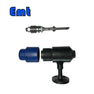
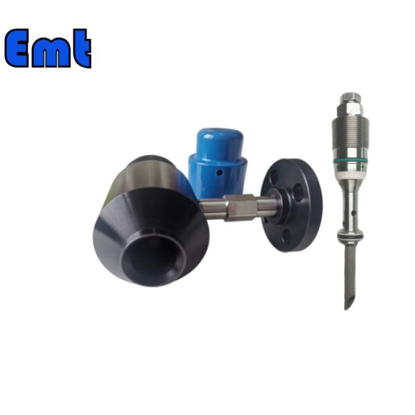
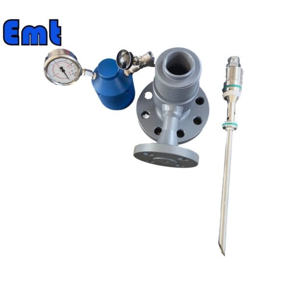
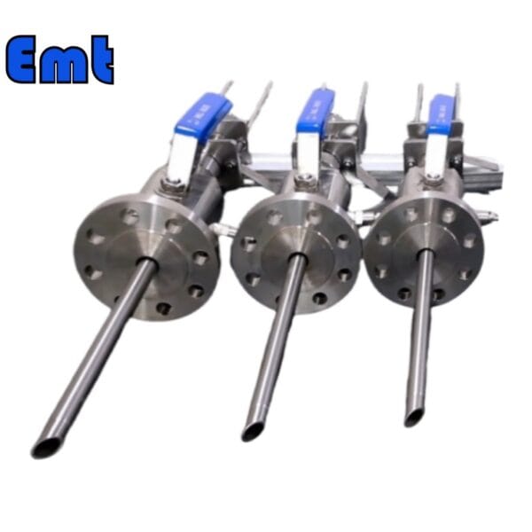
Device Constitution
The EMT Sampling Quill consists of a pedestal, protecting cover, plug, dropper support, dropper, connecting tube, and valve.
Application of the EMT Sampling Quill
Inject the chemical solution into the pipe through the valve and connecting tube by topping up the pump or withdrawing the medium in the pipe into the coupon vessel through connecting tube and valve.
Main Parameters
Specifications of connecting tube and valve (corresponding to T-type side hole of coupon injector): 1/4″1/2″3/4″1″
| Category | Details |
| Product Information | |
| Product Name | Sampling Quill |
| Brand Name | EMT Pigging |
| Condition | New |
| Type | Injection & Sampling System |
| Certification | ISO 9001 |
| Warranty | 1.5 years |
| Place of Origin | Liaoning, China |
| Physical Specifications | |
| Weight (KG) | 5 |
| Package Size (cm) | 35 x 40 x 60 |
| Gross Weight (Package, kg) | 8 |
| Material and Construction | |
| Sealing Material | Fluororubber |
| Solid Plug Assembly | 316L Stainless Steel |
| Injection Tube | 316L Stainless Steel |
| NPT Nozzle | 316L Stainless Steel |
| Flange Material | ASTM A105N |
| Operational Parameters | |
| Working Temperature (°C) | -20 to 200 |
| Operation Temperature (°C) | -20 to 150 |
| Working Pressure (LB) | 150LB, 300LB, 600LB, 900LB, 1500LB |
| Pressure Rating (PSI) | 6000 PSI or as per Flange Size |

Installation Method
Flange specification: ANSI 2″RF (or RJ)
Welded tube support: 2″
Sampler & Injector:
First, wrap the sealing strip at the thread end of the dropper, connect it to the NPT connection of the injection nut, and then screw it up.
Then put primary sealing packing on the screw of the plug with its big end toward the plug center. Link the other thread connection of the injection nut to the crew of the plug and tighten it, and then screw up the holding screw.
After that, fix the flange pedestal of the device on the mounting flange of the pipe temporarily (without tightening for the moment).
Then, fix the assembled injection assemblies of the plug on the flange pedestal and tighten it.
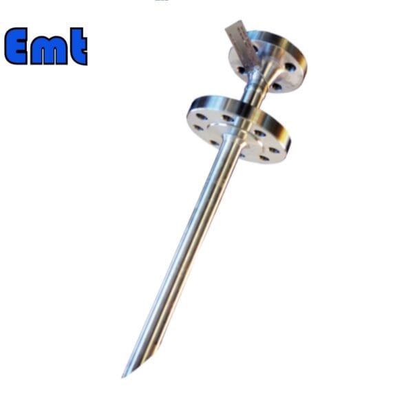
Loosen the connection with the mounting flange. Then take out the complete device, and make sure the orientation of the slope of the injection quill. Then adjust the orientation to let the slope of the injection quill over against the flow direction of the medium and Spray nozzle opposite. Measure or eye-measure the angle between the position of the Tee port or Tee flange adapter and the required position.
Remove the fitting body from the plug injection assemblies, rotate counterclockwise at a certain angle to loosen the fastening screw of the injection nut, then screw it up.
If the injection body is in Tee port shape, wrap the sealing strip at two ends of the NPT tube. You should connect one end to the T-type side opening on the flange pedestal and the other to the valve end, and screw up.
Attention
Operators should wear articles for labor protection. Besides, operators should carry out installation and operation following relative standards for instruments and equipment.
In case of under-pressure operation, any part of the operator’s body is not allowed to close to the interface port of the device. The destination is to prevent medium leakage and damage during operation.
EMT Sampling Quill Selection Model
| Model | |||||||||||||||||||||||||||
| SI | Chemical Injector Quill | ||||||||||||||||||||||||||
| -Code | Plug | ||||||||||||||||||||||||||
| Pxxx | Type | Material | Sealing Material | ||||||||||||||||||||||||
| 0 | No Request | 0 | CS | 0 | No Request | ||||||||||||||||||||||
| 1 | Hollow Plug Body | 1 | 316SS | 3 | DSS | 1 | Viton O-Ring / PTFE Primary Packing | ||||||||||||||||||||
| 2 | Solid Plug Body | 2 | 316LSS | 4 | INCONEL | 2 | HNBR | ||||||||||||||||||||
| – Code | Injection Nut | ||||||||||||||||||||||||||
| Nxx | Connection Size | Material | |||||||||||||||||||||||||
| 0 | i.e. No Request | 0 | i.e. CS | ||||||||||||||||||||||||
| 1 | i.e. 1/4″ | 1 | i.e. 316SS | 3 | i.e. DSS | ||||||||||||||||||||||
| 2 | i.e. 1/2″ | 2 | i.e. 316LSS | 4 | i.e. INCONEL | ||||||||||||||||||||||
| – Code | Injection Tube | ||||||||||||||||||||||||||
| Sxxx-Lx″ | Connection Size | Material | Nozzle | Line size(x″) | |||||||||||||||||||||||
| 0 | No Request | 0 | CS | 0 | i.e. No Request | The most effective position for injection is generally at the center of the pipe | |||||||||||||||||||||
| 1 | i.e. 1/4″ | 1 | i.e. 316SS | 1 | i.e. Open | ||||||||||||||||||||||
| 2 | i.e. 1/2″ | 2 | i.e. 316LSS | 2 | i.e. Quill | ||||||||||||||||||||||
| 3 | i.e. DSS | 3 | i.e. Cap & Core | ||||||||||||||||||||||||
| 4 | i.e. INCONEL | ||||||||||||||||||||||||||
| – Code | Nipple and Valve(or end Flange)of Tee | ||||||||||||||||||||||||||
| Txx | Connection Size | Material | |||||||||||||||||||||||||
| 0 | i.e. No Request | 0 | i.e. CS | ||||||||||||||||||||||||
| 1 | i.e. 1/4″Nipple | a | i.e. 1/4″Nipple and Valve | 1 | i.e. 316SS | ||||||||||||||||||||||
| 2 | i.e. 1/2″Nipple | b | i.e. 1/2″Nipple and Valve | 2 | i.e. 316LSS | ||||||||||||||||||||||
| 3 | i.e. 3/4″Nipple | c | i.e. 3/4″Nipple and Valve | 3 | i.e. D SS | ||||||||||||||||||||||
| 4 | i.e. 1″Nipple | d | i.e. 1″Nipple and Valve | 4 | i.e. INCONEL | ||||||||||||||||||||||
| 5 | i.e. 1/4″Flange | e | i.e. 1/4″Nipple end Flange | ||||||||||||||||||||||||
| 6 | i.e. 1/2″Flange | f | i.e. 1/2″Nipple end Flange | ||||||||||||||||||||||||
| 7 | i.e. 3/4″Flange | g | i.e. 3/4″Nipple end Flange | ||||||||||||||||||||||||
| 8 | i.e. 1″Flange | h | i.e. 1″Nipple end Flange | ||||||||||||||||||||||||
| For Example, SI-P221-N12-S122-L4″-T22 | |||||||||||||||||||||||||||
| SI:e.g. Sampling & Injection Assembly, | |||||||||||||||||||||||||||
| P221: e.g. Solid Plug Body in 316LSS Viton O-Ring and PTFE Primary Packing, | |||||||||||||||||||||||||||
| N12:e.g. injection Nut Connection Size is 1/4″and Material is 316LSS, | |||||||||||||||||||||||||||
| S122:e.g. injection Tube Connection Size is 1/4″ and Material is 316LSS. Type of nozzle is quills | |||||||||||||||||||||||||||
| L4″:For 4″pipe. | |||||||||||||||||||||||||||
| T22: Nipple of Tee Connection Size is 1/2″, Nipple material is 316LSS | |||||||||||||||||||||||||||
There are no reviews yet.