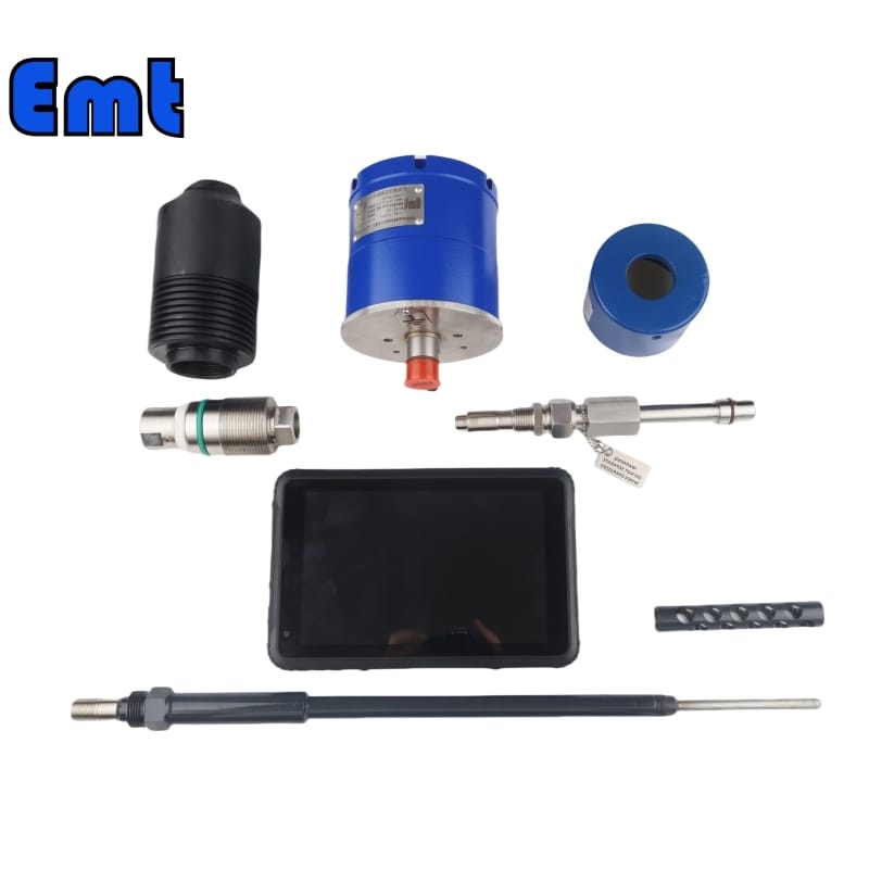
The EMT-EP100 model is a state-of-the-art cylindrical ER Corrosion Probe, specifically designed for deployment in high-pressure access systems. This probe’s unique construction and robust features make it exceptionally suited for monitoring corrosion in various industrial environments, particularly those involving harsh conditions.
Order Information
Access Fitting Body
| Model | ||||||
| EMT-CIPA | Access Fitting Body of ER Corrosion Probe | |||||
| – The material of Access Fitting Body | ||||||
| 0 | CS | |||||
| 1 | 316SS | |||||
| 2 | 316LSS | |||||
| 3 | DUPLEX SS | |||||
| The Type of Access Fitting Body | ||||||
| B | 2″Welded(suffix “pressure rating” can be added to B) | |||||
| F | 2″ANSI Flange(suffix “pressure rating & sealing type” can be added to F) | |||||
| -Tee Size- pressure rating & sealing type if flanged end | ||||||
| 0 | No Tee | |||||
| 1 | 1/4″NPT(F)Tee | |||||
| 2 | 1/2″NPT(F)Tee | |||||
| 3 | 3/4″NPT(F)Tee | |||||
| 4 | 1″NPT(F)Tee | |||||
| 5 | Hole for 1/4″SWN Flange | |||||
| 6 | Hole for 1/2″SWN Flange | |||||
| 7 | Hole for 3/4″SWN Flange | |||||
| 8 | Hole for 1″SWN Flange | |||||
| -Protective Cover Type/ Material | ||||||
| 0 | No Protective Cover | Material | ||||
| 1 | Without hole | CS or 0 | ||||
| 2 | With hole | SS or 1 | ||||
| 3 | Bleed Valve | DSS or 3 | ||||
| 4 | Bleed Valve, & Pressure Gauge | |||||
| For Example:EMT-CIPA-0F600#RF-0-2/CS shows 2″ANSI 600#RF Flange Access Fitting Body in CS, no Tee, Protective Cover in CS with hole 0F600#RF: 0F_ Access Fitting Body is Flanged in CS , 600#RF _Size is 2″ANSI 600#RF , 0:No Tee 2: Protective cover with 1/2NPT(F) hole /CS: Protective cove material in CS | ||||||
Cylindrical ER Corrosion Probe
| Model | |||||||||||
| EP100 | Cylindrical Electrical Resistance Corrosion Probe | ||||||||||
| -Code | Body Material | ||||||||||
| -B | 1 | 316 SS | |||||||||
| 2 | 316L SS | ||||||||||
| 3 | DUPLEX SS | ||||||||||
| 4 | INCONEL | ||||||||||
| -Code | Connector Type | ||||||||||
| -C | 1 | Standard connector | |||||||||
| 2 | Meet user requirements connector | ||||||||||
| -Code | ER Element Useful Thickness Options | ||||||||||
| -T | 10 | 10 mil thickness (5 mil useful probe life) | |||||||||
| 20 | 20 mil thickness (10 mil useful probe life) | ||||||||||
| 50 | 50 mil thickness (25 mil useful probe life) | ||||||||||
| Code | ER Probe Shield Options | ||||||||||
| -S | 0 | No shield DUPLEX SS INCONEL | |||||||||
| 1 | Standard shield | ||||||||||
| 2 | Hi-velocity shield | ||||||||||
| Code | Element Alloy Material | ||||||||||
| -xxx | Code | Probe Characteristic Length | |||||||||
| -xxx | mm | ||||||||||
| For Example:EP100-B1-C1-T20-S0-A105-358 EP100 : Cylindrical Electrical Resistance Corrosion Probe B1: Body Material is 316SS C1: Connector Type: Standard connector T20: ER Element is 20 mil thickness (10 mil useful probe life) S0: No shield A105: Element Alloy Material is A105 358:Probe length is 358mm | |||||||||||
Construction and Design
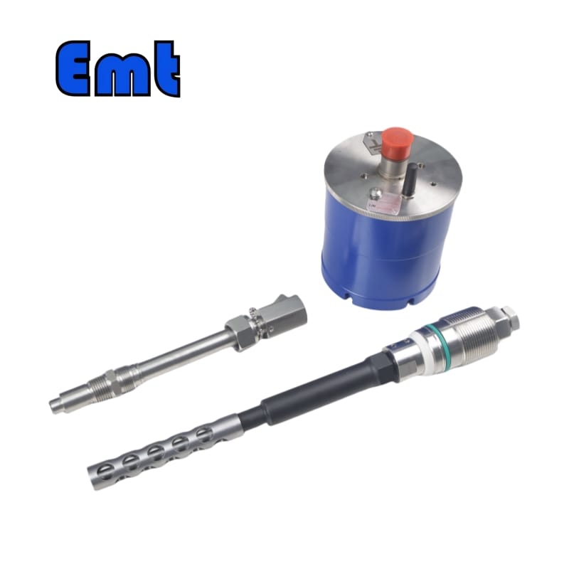
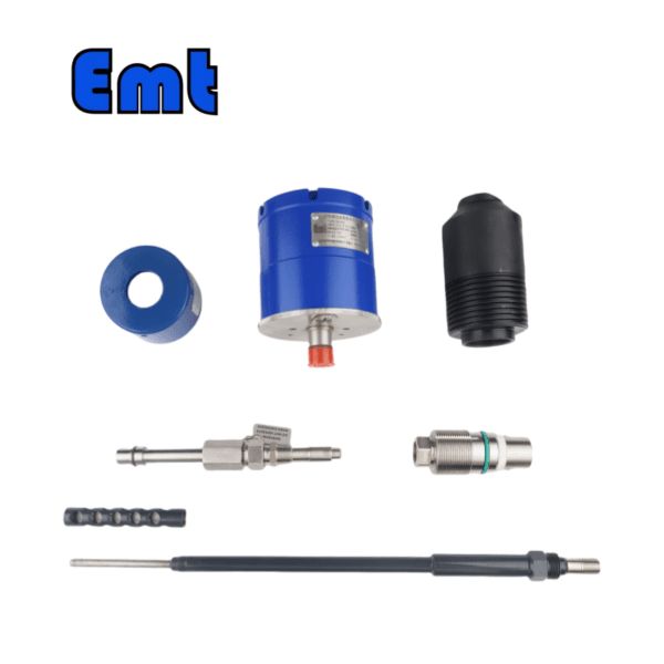
The EMT-EP ER Corrosion Probe features a fixed-length, retrievable design, ensuring both durability and ease of maintenance. It is crafted from high-quality materials such as 316 SS, 316L SS, DSS, and INCONEL, which are known for their resistance to corrosion and extreme environments. The probe’s fully welded structure enhances its integrity and suitability for use under severe operational conditions.
The physical assembly of the probe includes an extension rod that houses the sensing element, and a threaded connecting seat. A key aspect of the probe’s robust design is the integration of the measuring element with the probe body, which is achieved through advanced welding techniques. This integration ensures that there are no weak points where leaks might occur.
Sealing and Protection
To further enhance its reliability, the probe’s interface is sealed using high-temperature glass sintering. This method provides a superior seal that maintains its integrity under extreme temperatures, ranging from -200°C up to 450°C, depending on the selected specification. Inside the probe rod, a specially formulated filler is used, which possesses excellent heat and pressure resistance capabilities, safeguarding the internal components from the operational stress and environmental exposure.
For additional protection, the sensor element can be equipped with a protective cap, which helps prevent physical damage and contamination from the external environment.
Installation and Retrieval
Installation Overview
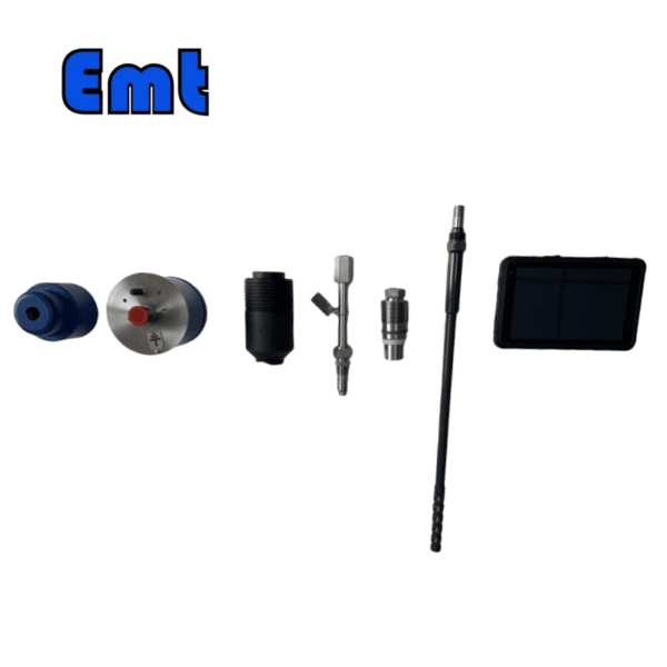
- Preparation: Ensure cleanliness and readiness of all components (probe, hollow plug, probe nut, sealing ring) and tools (retrieval tool, service valve).
- Mounting the Probe:
- Insert and align the probe into the hollow plug.
- Secure with the probe nut to specified torque and install the sealing ring for a leak-proof seal.
- Attaching to Process Line:
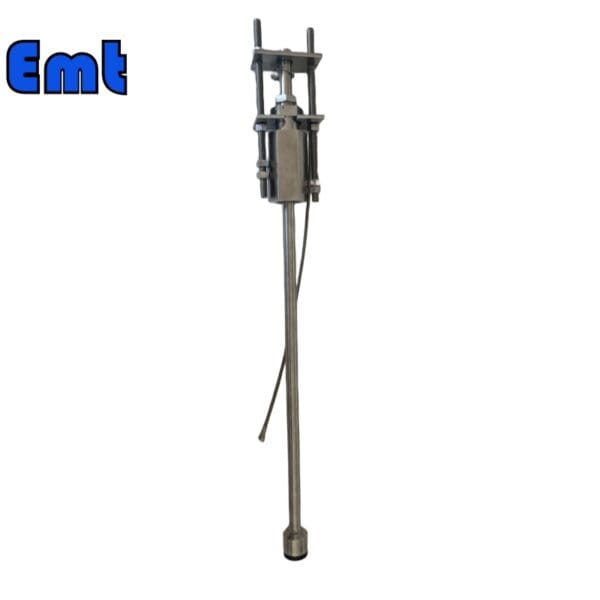
- Position and secure the probe-plug assembly using the retrieval tool and service valve at the process line access point.
- Perform a visual and functional test to confirm proper installation and operation.
Retrieval Overview
- Preparation for Retrieval:
- Stabilize and depressurize the section where the probe is installed to ensure safe removal conditions.
- Using the Retrieval Tool:
- Attach and use the tool to disengage and withdraw the probe-plug assembly.
- Maintenance and Inspection:
- Inspect and maintain the probe, plug, and sealing ring. Replace components as needed.
- Reinstallation (if applicable):
- Follow installation steps for placing the probe back into the system after maintenance, ensuring all components are secure and functional.
Additional Requirements
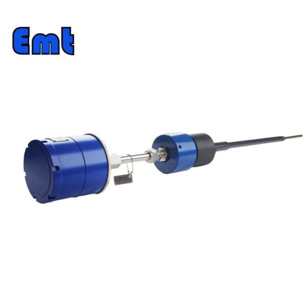
It is important to note that the probe requires an adapter to connect to the collector, which must be ordered separately. This adapter is crucial for the functional integration of the probe into the system, allowing for accurate data transmission and analysis.
There are no reviews yet.