
Introduction
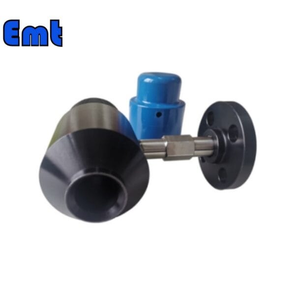
A Chemical Injection Quill is crucial in many industrial processes. It is especially important in the oil and gas sector. This device injects chemicals into pipelines or wellbores. It ensures chemicals reach the optimal depth and mix well with the process fluid. Effective mixing is key for corrosion control, scale prevention, and microbial management. Precise chemical application via quills is vital for pipeline integrity. It also boosts the overall efficiency of production processes.They are designed to withstand harsh conditions and high pressures, making them suitable for demanding environments.
Fossil fuels will remain essential to meet the needs of different industrial sectors around the world. Typically, only a third of the OOIP is recovered after the primary and secondary production phases. This means that about 70% of OOIP remains in the ground. Therefore, enhanced oil recovery is very important to release the remaining oil and gas resources in the reservoir.
Gas injection to enhance oil recovery (EOR) is the most commonly used technology to enhance oil recovery in light and medium reservoirs. This method can increase OOIP recovery by 10 to 25 percent, which is both cost-effective and relatively environmentally friendly. Especially compared with immiscible gas injection, miscible gas injection has higher sweep efficiency and oil displacement efficiency. Therefore, it has been the focus of the oil industry. In this context, the role of chemical injection quills becomes increasingly significant as they facilitate the precise and controlled delivery of specialty chemicals that can optimize the EOR processes.
Further Explanation
Several mechanisms can achieve high sweep and displacement efficiencies through gas drive. These include reducing oil viscosity, oil expansion, and lowering gas-oil interfacial tension (IFT). However, reaching miscibility is challenging for certain reservoirs, such as high-temperature or shallow ones. This challenge arises because the high pressures needed to reach the minimum miscibility pressure (MMP) between gas and oil phases might exceed the formation’s fracturing pressure.
Therefore, most miscible hydrocarbon gas injection projects follow specific criteria. These include using light crude oil (34-44 API), targeting reservoir depths of 4200-6700 feet, and operating at temperatures between 308K and 344K. In such scenarios, adding chemical additives, usually surfactants, to the oil and gas system can facilitate the miscibility process. This addition might transform non-miscible conditions into miscible or near-miscible injection conditions, thus broadening the scope of miscible hydrocarbon gas injection to more reserves.
This approach benefits high-temperature reservoirs where MMP increases with temperature. However, it limits the maximum allowable injection pressure in shallow reservoirs with low formation fracturing pressures. Thus, using chemical additives to lower the oil-gas MMP is a promising technique. It reduces interfacial tension and enhances oil recovery efficiency, potentially boosting crude oil recovery rates.
Inhibitor for Chemical Injection Quill
Current literature shows that adding chemical additives like surfactants, alcohols, and carboxylic acids to CO2-petroleum systems can lower MMP by up to 22%. These additives range in concentration from 0.1 wt% to 10 wt%. Additionally, surfactants with CO2-philic groups, such as polyethylene oxide and polypropylene oxide, prove most effective in enhancing compatibility in these systems.
However, research on lowering MMP in natural gas-petroleum systems remains scarce and challenging. Unlike methods with carbon dioxide, these techniques can significantly increase the initial MMP, approximately two to three times. This increase allows for injecting non-miscible gases under in-situ reservoir conditions, leading to higher residual oil saturation.
Therefore, it is crucial to explore adding chemical additives or other gases to enrich natural gas and assist the miscibility process. This approach aims to achieve the miscibility of natural gas with crude oil at lower pressures. Besides being low-cost and readily available, using produced natural gas through reinjection/recycling rather than burning or emitting offers clear environmental benefits. It helps reduce greenhouse gas emissions and supports the goal of achieving net-zero carbon emissions.
Previous studies used interfacial tension measurements to study the effects of different surfactants and alcohol-based chemicals on methane-oil miscibility. Similar to the CO2-crude oil system, the results showed that surfactant-based chemicals performed better than alcohols, achieving a higher MMP reduction rate. Specifically, adding nonionic alkoxylated surfactants to the methane-oil system at 373K reduced MMP by up to 9%.

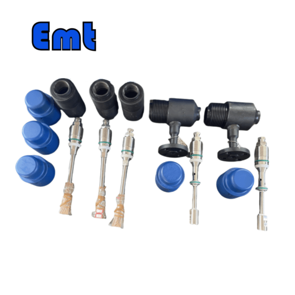
EMT Chemical Injection Quill Selection
| Model | |||||||||||||||||||||||||||
| SI | Chemical Injector Quill | ||||||||||||||||||||||||||
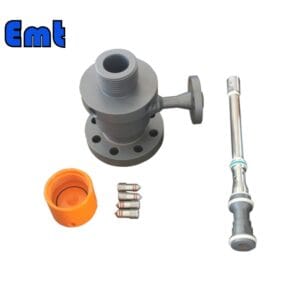
| -Code | Plug | ||||||||||||||||||||||||||
| Pxxx | Type | Material | Sealing Material | ||||||||||||||||||||||||
| 0 | No Request | 0 | CS | 0 | No Request | ||||||||||||||||||||||
| 1 | Hollow Plug Body | 1 | 316SS | 3 | DSS | 1 | Viton O-Ring / PTFE Primary Packing | ||||||||||||||||||||
| 2 | Solid Plug Body | 2 | 316LSS | 4 | INCONEL | 2 | HNBR | ||||||||||||||||||||
| – Code | Injection Nut | ||||||||||||||||||||||||||
| Nxx | Connection Size | Material | |||||||||||||||||||||||||
| 0 | i.e. No Request | 0 | i.e. CS | ||||||||||||||||||||||||
| 1 | i.e. 1/4″ | 1 | i.e. 316SS | 3 | i.e. DSS | ||||||||||||||||||||||
| 2 | i.e. 1/2″ | 2 | i.e. 316LSS | 4 | i.e. INCONEL | ||||||||||||||||||||||
| – Code | Injection Tube | ||||||||||||||||||||||||||
| Sxxx-Lx″ | Connection Size | Material | Nozzle | Line size(x″) | |||||||||||||||||||||||
| 0 | No Request | 0 | CS | 0 | i.e. No Request | The most effective position for injection is generally at the center of the pipe | |||||||||||||||||||||
| 1 | i.e. 1/4″ | 1 | i.e. 316SS | 1 | i.e. Open | ||||||||||||||||||||||
| 2 | i.e. 1/2″ | 2 | i.e. 316LSS | 2 | i.e. Quill | ||||||||||||||||||||||
| 3 | i.e. DSS | 3 | i.e. Cap & Core | ||||||||||||||||||||||||
| 4 | i.e. INCONEL | ||||||||||||||||||||||||||
| – Code | Nipple and Valve(or end Flange)of Tee | ||||||||||||||||||||||||||
| Txx | Connection Size | Material | |||||||||||||||||||||||||
| 0 | i.e. No Request | 0 | i.e. CS | ||||||||||||||||||||||||
| 1 | i.e. 1/4″Nipple | a | i.e. 1/4″Nipple and Valve | 1 | i.e. 316SS | ||||||||||||||||||||||
| 2 | i.e. 1/2″Nipple | b | i.e. 1/2″Nipple and Valve | 2 | i.e. 316LSS | ||||||||||||||||||||||
| 3 | i.e. 3/4″Nipple | c | i.e. 3/4″Nipple and Valve | 3 | i.e. D SS | ||||||||||||||||||||||
| 4 | i.e. 1″Nipple | d | i.e. 1″Nipple and Valve | 4 | i.e. INCONEL | ||||||||||||||||||||||
| 5 | i.e. 1/4″Flange | e | i.e. 1/4″Nipple end Flange | ||||||||||||||||||||||||
| 6 | i.e. 1/2″Flange | f | i.e. 1/2″Nipple end Flange | ||||||||||||||||||||||||
| 7 | i.e. 3/4″Flange | g | i.e. 3/4″Nipple end Flange | ||||||||||||||||||||||||
| 8 | i.e. 1″Flange | h | i.e. 1″Nipple end Flange | ||||||||||||||||||||||||
| For Example, SI-P221-N12-S122-L4″-T22 | |||||||||||||||||||||||||||
| SI:e.g. Sampling & Injection Assembly, | |||||||||||||||||||||||||||
| P221: e.g. Solid Plug Body in 316LSS Viton O-Ring and PTFE Primary Packing, | |||||||||||||||||||||||||||
| N12:e.g. injection Nut Connection Size is 1/4″and Material is 316LSS, | |||||||||||||||||||||||||||
| S122:e.g. injection Tube Connection Size is 1/4″ and Material is 316LSS. Type of nozzle is quills | |||||||||||||||||||||||||||
| L4″:For 4″pipe. | |||||||||||||||||||||||||||
| T22: Nipple of Tee Connection Size is 1/2″, Nipple material is 316LSS | |||||||||||||||||||||||||||
There are no reviews yet.