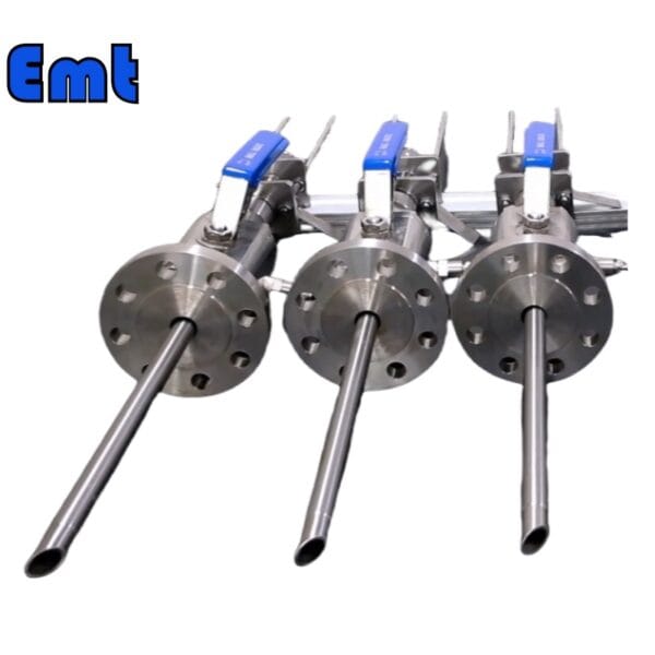
1. Chemical Injection EMT-CI
The Chemical Injection EMT-CI system is a crucial component in maintaining pipeline integrity and efficiency through the controlled injection of chemical inhibitors. Designed to combat corrosion within pipelines, this system allows for the periodic introduction of chemicals directly into the pipeline under operational pressures. The system’s design ensures reliability, safety, and ease of access for both maintenance and operation.
2. Key Features of the Chemical Injection
Chemical Injection:
- Versatile Nozzle Options: The EMT-CI system accommodates various nozzle types, allowing customization based on specific injection requirements and pipeline characteristics.
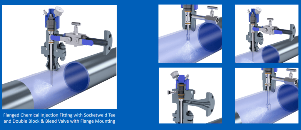
- Safe and Controlled Injection: Chemicals can be injected safely under operating pressure, ensuring continuous protection against corrosion without interrupting pipeline operation.
- High-Pressure Capability: The system is designed to handle pressures up to 6000 PSI, making it suitable for high-pressure pipeline environments.
Sampler:
- Integration with Injector: The sampler component mirrors the functionality and design of the injector, enabling consistent and accurate sampling of the pipeline medium for monitoring and analysis.
- Easy Access and Operation: Like the injector, the sampler is designed for ease of use, allowing for quick and reliable access to pipeline contents.
Mounting Options:
- Versatile Mounting Solutions: The system can be mounted using a 2-inch flange or a 2-inch Flareweld access fitting, providing flexibility in installation. Additionally, a 1-inch Nipple to NPT ball valve option is available, catering to different system requirements and pipeline configurations.
Operating Conditions:
- Temperature Range: The EMT-CI system is capable of operating in environments with temperatures ranging from -20 ℃ to 150 ℃, accommodating various climatic conditions and pipeline operations.
- Pressure Rating: The system’s compatibility with a pressure rating of 6000 PSI or the applicable flange size ensures it can withstand the rigorous pressures typically found in pipeline systems.
3. Benefits
- Corrosion Control: By facilitating the injection of inhibitors, the system helps minimize corrosion, thereby extending the lifespan of the pipeline.
- Operational Safety: The design and construction of the system prioritize safety, with features that allow for chemical handling under pressure without risk.
- Maintenance Efficiency: Easy access to system components reduces downtime and enhances the efficiency of maintenance procedures.
- Versatility: The range of mounting and nozzle options, along with the system’s high-pressure capability, makes it adaptable to various pipeline specifications and operational needs.
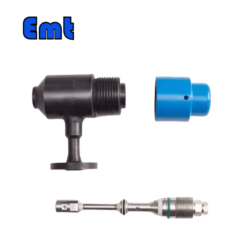
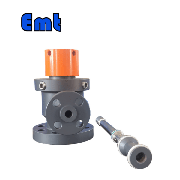
4. Access Fitting Body
| Model | ||||||
| EMT-CIPA | Access Fitting Body | |||||
| – The material of Access Fitting Body | ||||||
| 0 | CS | |||||
| 1 | 316SS | |||||
| 2 | 316LSS | |||||
| 3 | DUPLEX SS | |||||
| The Type of Access Fitting Body | ||||||
| B | 2″Welded(suffix “pressure rating & pipe size” can be added to B) | |||||
| F | 2″ANSI Flange(suffix “pressure rating & sealing type” can be added to F) | |||||
| -Tee Size- pressure rating & sealing type if flanged end | ||||||
| 0 | No Tee | |||||
| 1 | 1/4″Tee | |||||
| 2 | 1/2″Tee | |||||
| 3 | 3/4″Tee | |||||
| 4 | 1″Tee | |||||
| -Protective Cover Type/ Material | ||||||
| 0 | No Protective Cover | Material | ||||
| 1 | Without hole | CS or 0 | ||||
| 2 | With hole | SS or 1 | ||||
| 3 | Bleed Valve | DSS or 3 | ||||
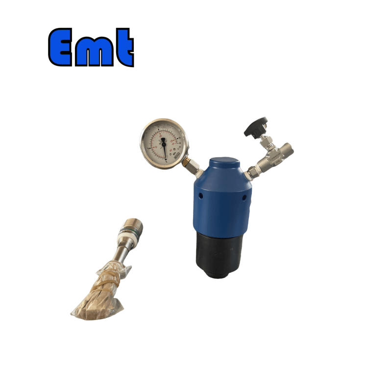
| 4 | Bleed Valve, & Pressure Gauge | |||||
| For Example:EMT-CIPA-0F600#RF-2-1/CS shows 2″ANSI 600#RF Flange Access Fitting Body in CS, 1/2″NPT(F)Tee, Protective Cover in CS without hole 0F600#RF: 0F_ Access Fitting Body is Flanged in CS , 600#RF _Size is 2″ANSI 600#RF , 2:Tee size is 1/2NPT(F) 1: Protective cover type is without hole /CS: Material in CS | ||||||
Sampling & Injection Point
| Model | ||||||||||||||||||||||||||||
| SI | Sampling & Injection Assembly | |||||||||||||||||||||||||||
| -Code | Plug | |||||||||||||||||||||||||||
| Pxxx | Type | Material | Sealing Material | |||||||||||||||||||||||||
| 0 | No Request | 0 | CS | 0 | No Request | |||||||||||||||||||||||
| 1 | Hollow Plug Body | 1 | 316SS | 3 | DSS | 1 | Viton O-Ring / PTFE Primary Packing | |||||||||||||||||||||
| 2 | Solid Plug Body | 2 | 316LSS | 4 | INCONEL | 2 | HNBR | |||||||||||||||||||||
| – Code | Injection Nut | |||||||||||||||||||||||||||
| Nxx | Connection Size | Material | ||||||||||||||||||||||||||
| 0 | No Request | 0 | CS | |||||||||||||||||||||||||
| 1 | 1/4″ | 1 | 316SS | 3 | DSS | |||||||||||||||||||||||
| 2 | 1/2″ | 2 | 316LSS | 4 | INCONEL | |||||||||||||||||||||||
| – Code | Injection Tube | |||||||||||||||||||||||||||
| Sxxx-Lx″ | Connection Size | Material | Nozzle | Line size(x″) | ||||||||||||||||||||||||
| 0 | No Request | 0 | CS | 0 | No Request | The most effective position for injection is generally at the center of the pipe | ||||||||||||||||||||||
| 1 | 1/4″ | 1 | 316SS | 1 | Open | |||||||||||||||||||||||
| 2 | 1/2″ | 2 | 316LSS | 2 | Quill | |||||||||||||||||||||||
| 3 | DSS | 3 | Cap & Core | |||||||||||||||||||||||||
| 4 | INCONEL | |||||||||||||||||||||||||||
| – Code | Nipple and Valve(or end Flange)of Tee | |||||||||||||||||||||||||||
| Txx | Connection Size | Material | ||||||||||||||||||||||||||
| 0 | No Request | 0 | CS | |||||||||||||||||||||||||
| 1 | 1/4″Nipple | a | 1/4″Nipple and Valve | 1 | 316SS | |||||||||||||||||||||||
| 2 | 1/2″Nipple | b | 1/2″Nipple and Valve | 2 | 316LSS | |||||||||||||||||||||||
| 3 | 3/4″Nipple | c | 3/4″Nipple and Valve | 3 | D SS | |||||||||||||||||||||||
| 4 | 1″Nipple | d | 1″Nipple and Valve | 4 | INCONEL | |||||||||||||||||||||||
| 5 | 1/4″Flange | e | 1/4″Nipple end Flange | |||||||||||||||||||||||||
| 6 | 1/2″Flange | f | 1/2″Nipple end Flange | |||||||||||||||||||||||||
| 7 | 3/4″Flange | g | 3/4″Nipple end Flange | |||||||||||||||||||||||||
| 8 | 1″Flange | h | 1″Nipple end Flange | |||||||||||||||||||||||||
| For Example:SI-P221-N12-S122-L4″-T22 SI:Sampling & Injection Assembly,P221: Solid Plug Body in 316LSS Viton O-Ring and PTFE Primary Packing,N12:Injection Nut Connection Size is 1/4″and Material is 316LSS,S122:Injection Tube Connection Size is 1/4″ and Material is 316LSS.Type of nozzle is quill,L4″:For 4″pipe. T22: Nipple of Tee Connection Size is 1/2″, Nipple material is 316LSS | ||||||||||||||||||||||||||||
A set of Sampling & Injection Systems:
EMT-CIPA-0F600#RF-2-1+ SI-P221-N12-S122-L4″-T22
The Chemical Injection EMT-CI system is an integral part of maintaining pipeline functionality and integrity, providing a robust solution for the challenges of corrosion and pipeline management in industrial applications.


There are no reviews yet.