
A chemical injection quill assembly is critical in many industrial processes, especially in oil and gas, chemical manufacturing, and water treatment. Designers create this device to introduce precise chemical amounts into a pipeline or vessel. This ensures efficient mixing and dispersion within the fluid stream.
Key Components of a Chemical Injection Quill Assembly
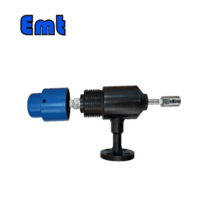
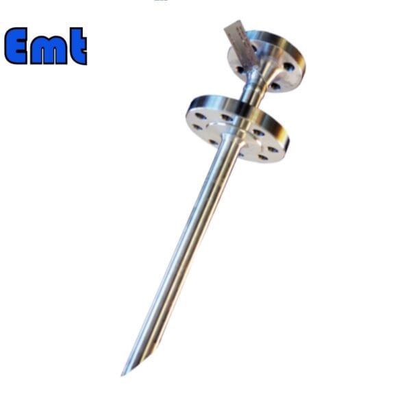
Quill: The quill is a long, narrow tube that extends into the pipeline. It allows chemicals to be injected directly into the center of the flow. This placement ensures rapid mixing and reduces the exposure of the pipeline walls to potentially corrosive chemicals.
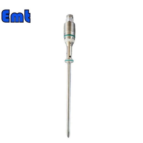
Check Valve: Integrated into the assembly to prevent the backflow of the pipeline contents into the chemical supply, protecting both the supply and the injection system.
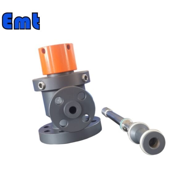
Isolation Valve: Used to isolate the injection point from the main pipeline for maintenance or in case of a malfunction.
Valve Operation: Operators can close this valve to safely service the quill without interrupting the pipeline operation.
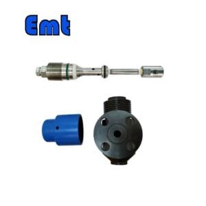
Injection Point: The location on the pipeline where operators insert the quill. It is typically designed for easy access and secure attachment to ensure a leak-proof connection.
Connection Fittings: Operators use these fittings to securely connect the quill to the chemical supply lines. The fittings must be compatible with both the chemicals being used and the materials of construction of the pipeline to avoid corrosion or degradation.
Advantages of Using a Chemical Injection Quill
Efficiency: The direct injection into the flow stream ensures immediate mixing and reaction, improving the overall efficiency of the chemical usage.
Safety: Reduces operator exposure to chemicals and minimizes the risk of leaks or spills at the injection site.
Precision: Allows for precise control over the amount and rate of chemical introduced, which is critical for maintaining process parameters and ensuring quality control.
Selection Model
| Model | |||||||||||||||||||||||||||
| SI | Chemical Injector Quill | ||||||||||||||||||||||||||
| -Code | Plug | ||||||||||||||||||||||||||
| Pxxx | Type | Material | Sealing Material | ||||||||||||||||||||||||
| 0 | No Request | 0 | CS | 0 | No Request | ||||||||||||||||||||||
| 1 | Hollow Plug Body | 1 | 316SS | 3 | DSS | 1 | Viton O-Ring / PTFE Primary Packing | ||||||||||||||||||||
| 2 | Solid Plug Body | 2 | 316LSS | 4 | INCONEL | 2 | HNBR | ||||||||||||||||||||
| – Code | Injection Nut | ||||||||||||||||||||||||||
| Nxx | Connection Size | Material | |||||||||||||||||||||||||
| 0 | i.e. No Request | 0 | i.e. CS | ||||||||||||||||||||||||
| 1 | i.e. 1/4″ | 1 | i.e. 316SS | 3 | i.e. DSS | ||||||||||||||||||||||
| 2 | i.e. 1/2″ | 2 | i.e. 316LSS | 4 | i.e. INCONEL | ||||||||||||||||||||||
| – Code | Injection Tube | ||||||||||||||||||||||||||
| Sxxx-Lx″ | Connection Size | Material | Nozzle | Line size(x″) | |||||||||||||||||||||||
| 0 | No Request | 0 | CS | 0 | i.e. No Request | The most effective position for injection is generally at the center of the pipe | |||||||||||||||||||||
| 1 | i.e. 1/4″ | 1 | i.e. 316SS | 1 | i.e. Open | ||||||||||||||||||||||
| 2 | i.e. 1/2″ | 2 | i.e. 316LSS | 2 | i.e. Quill | ||||||||||||||||||||||
| 3 | i.e. DSS | 3 | i.e. Cap & Core | ||||||||||||||||||||||||
| 4 | i.e. INCONEL | ||||||||||||||||||||||||||
| – Code | Nipple and Valve(or end Flange)of Tee | ||||||||||||||||||||||||||
| Txx | Connection Size | Material | |||||||||||||||||||||||||
| 0 | i.e. No Request | 0 | i.e. CS | ||||||||||||||||||||||||
| 1 | i.e. 1/4″Nipple | a | i.e. 1/4″Nipple and Valve | 1 | i.e. 316SS | ||||||||||||||||||||||
| 2 | i.e. 1/2″Nipple | b | i.e. 1/2″Nipple and Valve | 2 | i.e. 316LSS | ||||||||||||||||||||||
| 3 | i.e. 3/4″Nipple | c | i.e. 3/4″Nipple and Valve | 3 | i.e. D SS | ||||||||||||||||||||||
| 4 | i.e. 1″Nipple | d | i.e. 1″Nipple and Valve | 4 | i.e. INCONEL | ||||||||||||||||||||||
| 5 | i.e. 1/4″Flange | e | i.e. 1/4″Nipple end Flange | ||||||||||||||||||||||||
| 6 | i.e. 1/2″Flange | f | i.e. 1/2″Nipple end Flange | ||||||||||||||||||||||||
| 7 | i.e. 3/4″Flange | g | i.e. 3/4″Nipple end Flange | ||||||||||||||||||||||||
| 8 | i.e. 1″Flange | h | i.e. 1″Nipple end Flange | ||||||||||||||||||||||||
| For Example, SI-P221-N12-S122-L4″-T22 | |||||||||||||||||||||||||||
What is a Chemical Injection Quill?
A chemical injection quill injects chemicals directly into a pipeline or vessel at a specific point in various industrial processes. This device ensures even chemical distribution within the fluid stream. It enhances efficiency and effectiveness in chemical reactions or treatments. Industries like water treatment and oil and gas production commonly use chemical injection quills for precise dosing.
gel
How Does a Chemical Injection Quill Work?
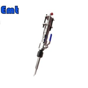
A chemical injection quill typically consists of a long, narrow tube that extends into the pipeline or vessel. Its design enables direct chemical injection into the flow’s center, which promotes rapid mixing and dispersal with the process fluid. Here’s a detailed breakdown of its operation:
Positioning: Initially, operators mount the quill through the wall, securing it with a flanged or threaded connection for a leak-proof system.
Injection Point: Subsequently, the tip releases chemicals, strategically positioned away from the wall and close to the flow’s center.
Distribution: This placement aids significantly in achieving a more uniform distribution of the chemicals in the fluid stream.
Backflow Prevention: Moreover, a check valve, often integrated into the quill, prevents the process fluid from entering the chemical supply line. This step is crucial for maintaining the purity of the chemical and ensuring safety.
Controlled Delivery: Finally, operators regulate chemical flow through the quill with valves, controlled by automated systems using real-time sensor data. This allows for precise adjustments to meet customer needs.
Parameters
| Category | Details |
| Product Information | |
| Product Name | Chemical Injection Quill |
| Brand Name | EMT Pigging |
| Condition | New |
| Type | Injection & Sampling System |
| Certification | ISO 9001 |
| Warranty | 1.5 years |
| Place of Origin | Liaoning, China |
| Physical Specifications | |
| Weight (KG) | 5 |
| Package Size (cm) | 35 x 40 x 60 |
| Gross Weight (Package, kg) | 8 |
| Material and Construction | |
| Sealing Material | Fluororubber |
| Solid Plug Assembly | 316L Stainless Steel |
| Injection Tube | 316L Stainless Steel |
| NPT Nozzle | 316L Stainless Steel |
| Flange Material | ASTM A105N |
| Operational Parameters | |
| Working Temperature (°C) | -20 to 200 |
| Operation Temperature (°C) | -20 to 150 |
| Working Pressure (LB) | 150LB, 300LB, 600LB, 900LB, 1500LB |
| Pressure Rating (PSI) | 6000 PSI or as per Flange Size |

There are no reviews yet.